BPA 600 Conductive Testing
Test Equipment
While exact conductive test setups are dependent on the specific circumstances surrounding the DUT RF interface, the following equipment is required for all test setups.
- Coaxial cable with adapter for connecting to DUT 1.
- Coaxial cable with adapter for connecting to DUT 2.
- 2 Coaxial T-connectors.
- 2 SMA adapters for connecting coaxial cable or attenuators to the BPA 600 antenna connectors.
- Attenuators depending on the Bluetooth Class being tested.
- Frontline BPA 600 Dual Mode Bluetooth Protocol Analyzer
- Personal computer for running Frontline software.
Test Set Up
"BPA 600 Conductive Test Setup" shows the test setup.
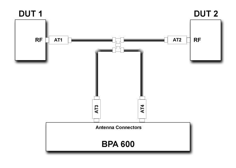
Both ComProbe BPA 600 antennas must be connected as shown.
The AT1 through AT4 attenuator values will depend on the DUT1 and DUT2 transmitter Class. At higher power levels all four attenuators may be needed. In all cases, use good engineering practices to protect the devices under test and the ComProbe hardware from damage, and to ensure reliable operation.
Assuming that there is no attenuation in the test setup:
- At each T-connector the power will split in half. Therefore the power reaching the BPA 600 protocol analyzer will be one-fourth the transmitted power. For example if DUT 1 is a Class 1 device transmitting +20 dBm (100 mW), at the first T-connector it will split with +17 dBm (50 mW) going to DUT2 and +17dBm (50 mW) going to the ComProbe analyzer.
- The +17dBm (50 mW) going to the ComProbe analyzer splits again. Each coaxial cable going to a ComProbe analyzer antenna connector carries +14 dBm (25 mW).
- If DUT1 or DUT2 is a Class 2 device, +8 dBm (6.25 mW) will reach each ComProbe analyzer antenna connector. If they are Class 3 devices, -6 dBm (0.25 mW) will reach each antenna connector.
- Attenuation should be selected to limit the received power levels to prevent equipment damage, and to provide sufficient power to reliably operate the equipment. If using attenuation follow these recommendations:
- If the devices are of the same class, the attenuators AT1 and AT2 should be of equal value.
- Attenuators AT3 and AT4 should be of equal value.
- Determine the maximum power received at the ComProbe antenna jacks. Then select an appropriate attenuator value to limit the input power to -20 dBm (10 μW) maximum.